![]()
|
"How-To
Projects"
|
|
| --- LIGHTPENS --- | |
|
Modified Vectrex Lightpen
(MVLP) by Brett Walach & Rob Mitchell & |
OK, so you don't want to spend 3 hours or even $10 for
a lightpen, and you don't care if it's the "official" Vectrex
lightpen circuit? This is the next best thing! Works just as good (if
not better) than the original, and it's sooo easy to build. You'll be
wanting to build one for all of your friends, and pretty soon so many
people will have lightpens...and be longing for a NEW lightpen game!
;)
|
|
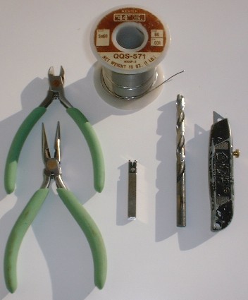
Supplies Needed Electric Drill and a 1/4" Drill Bit
|
|
|
Components Needed R1 10k (BrownBlackOrangeGold) C1 0.01µF (#103 Ceramic, 10v or higher) |
|
|
Time Required It took me about 1 hour to build from the time I had everything laid out. I took my time and made sure to highlight all of the connections on the schematic as I wired them up. It's very hard to get it right the first time with projects like this, but with this one it worked right away. Thoroughness pays off in the end. Actually, this one is fairly simple, and you could probably get it done in less time if you didn't care about the cosmetic apperance of the lightpen. |
|
| * Marker Casing * |
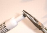
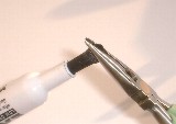
BUILD IT - STEP BY STEP |
    Click Any Pic Above For Larger View |
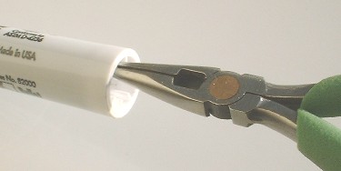
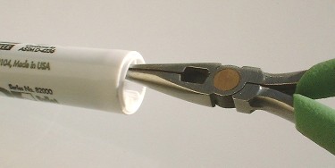
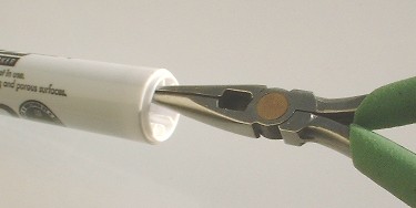
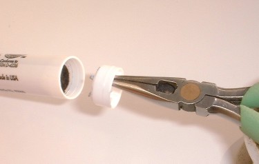
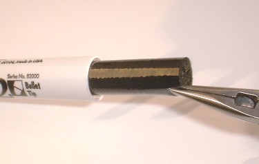
Take your needle nose pliers and carefully remove the endcap on the marker. Grab one of the fins and first twist it around to loosen it up. Pull out on one of the fins until it pops the endcap out a little, then pop out the opposite side. The endcap should be loose enough now to pull it off. If this approach doesn't work, apply an outward pull at the same time you are rotating it. If you pull too hard, the fin you are grabbing will rip off. If you break one, it's probably ok because you'll be filling this area with hot glue later. Just don't break too many off or you won't have anything left for the hot glue to stick to. |
 Click For Big Picture |
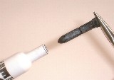
Remove the ink filled wadding and toss it in the trash. |
|
|
Remove the marker's felt tip with with the needle nose pliers by grabbing it firmly and pulling it straight out. If it gives you trouble, twist it as you pull. Then toss it. Be careful not to mar the marker case tip, as this will be touching your Vectrex screen. You want to keep this case tip smooth. |
| Use your imagination | Rinse out the case so it's nice and clean. Twist up a papertowel and shove it in there if you want to get it squeaky clean. |
| Now it's time to remove the printed text on the marker. Usually a good solvent is needed here. I've used PCB Flux Remover which comes in an aerosol can. Spray some onto a papertowel and rub the case firmly. The text will start to disappear after a little elbow grease. If you don't have Flux Remover, you may need to use something with acetone in it, or just acetone itself. Be very careful with acetone!! Read the warnings, I can't tell you everything. Acetone will dry out your hands, dissolve styrofoam, and take paint off of almost anything... but it's not as harmful as say... paint stripper. Be careful with it though. | |
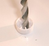 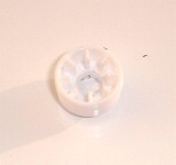 |
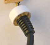
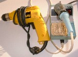
Prepare the endcap. You need
to drill a hole through the endcap so you can feed the 9 pin cable through
it. Depending on which cable you have, and what the strain relief looks
like, you may need to drill different size holes here. I found that a
1/4" hole works well. [UPDATE] Theodore Mason has suggested an alternative preparation for the endcap so you will no need to secure the cable with hotglue in a later step. By cutting a square hole in the endcap and a slit down one side, the endcap can be flexed open to accept the square cable strain relief. Once the endcap is snapped into the end of the marker casing, the cable will be locked in place without the need for hotglue. 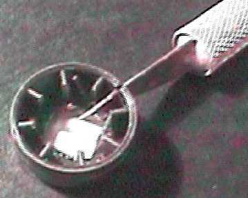
Click For Big Picture |
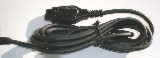
| * 9 Pin Cable * | |
|
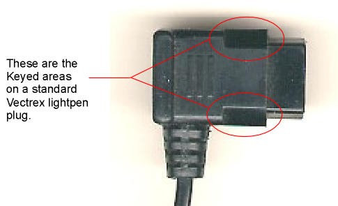
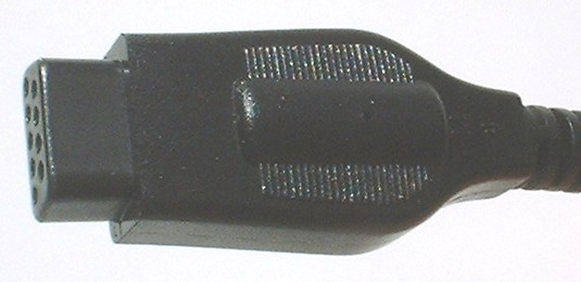
Vectrex Plug |
Prepare the plug. Trim back the sides of the plug as shown in the picture. Use your Vectrex controller plug as a reference as you do this. |
| No Pic Availible | Verify and prepare the 3 wires you need (+5v, GND, & SW7) and cut off the rest. Something I like to do when I cut off a bunch of wires next to each other is to pull up the insulation a bit with a pair of needle nose pliers. This protects against the wires shorting together... and there are some wires you wouldn't want shorted together that are left over. If you want to be extra safe, use some electrical tape to isolate each wire from the next, or you could try heat shrinking each one. Do whatever you think is right for you and your Vec. Protect your investment. |
|
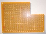
* Protoboard *
|
|
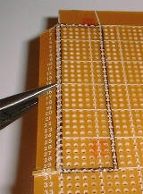
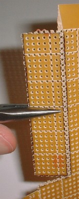
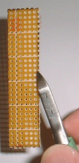
| Prepare the protoboard, also known as perfboard to all you techies out there. Refer to the diagram for the proper dimensions and hole spacing. Cut this using a metal bladed hacksaw or score it with a razor knife and snap it. You can also use wire cutters to nibble away at the protoboard. Just snip off a little at a time. When you're done cutting out the rough shape, you will most likely have to use some 120 grit sandpaper to take down the edges. If it's too much to sand, then start snipping some more. You may notice that the "dimensions" image shows two different measurements on the narrow ends of the board. This is because the marker case slightly tapers down towards the TIP. Keep the maker casing nearby so you can test fit it as you fine tune the protoboard by sanding the edges. If you sand down the board to the dimensions in the diagram, and you are using the same marker casing, the fit should be perfect. | |
|
* Parts * |
STEP 2. Build It! |
|
No Pic Availible
|
Lay out your parts so they are easy to find. There's only 8 components in this circuit so it shouldn't be too big of a deal. Use a small dish or bowl to hold your components if you wish. |
|
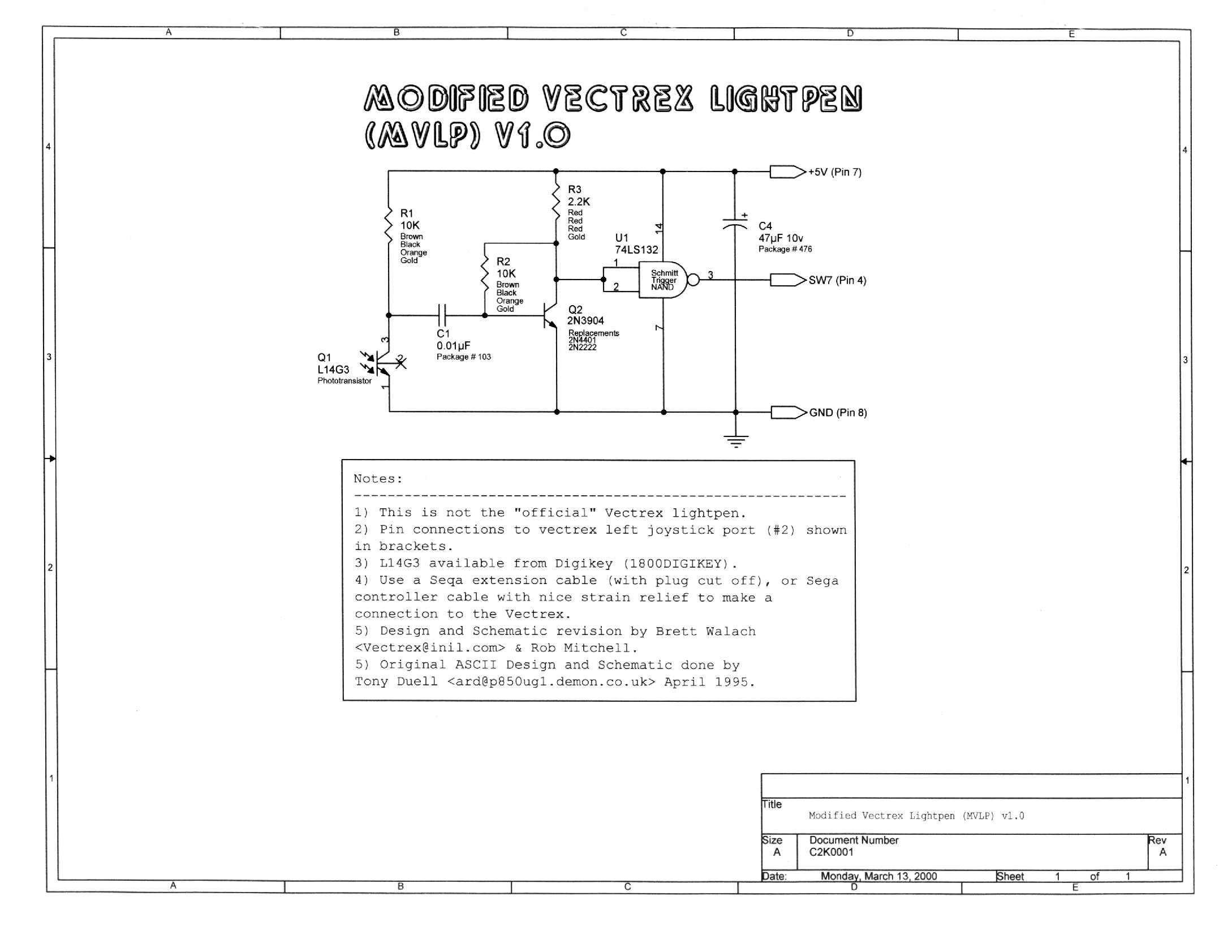
* Schematic *
|
|
|
[200 DPI Versions] MVLPv10_200DPI.pdf, 142Ki MVLPv10_300DPI.pdf, 255Ki |
Print out a schematic so you have a "blueprint" to construct this circuit from. I find it particularly convienent to highlight each component I insert, and each node I connect as I'm wiring it all together. This may not be necessary for a circuit as small as this, but I always do it to consistently build circuits right the first time. This minimizes debug of the final circuit to practically nothing. Don't say I never offered a diverse selection of file types ;) Grab a 300 DPI version if you want superb print-a-blility! Grab the DXF if you have a 28.8bps modem :( |
| * Populate The Protoboard * | |
|
Layout Diagram Click For Big Picture Click For Big Picture |
Now it's time to insert the 8 components into the protoboard and solder them in place. You can refer to the layout diagram for the parts layout that I use, or you can design your own. |
| * Wire It Up * | |
Click For Big Picture |
OK, since we want this thing to fit inside a small marker casing, you can't use wirewrap sockets for the components, so you'll have to solder the connections point-to-point style. Just use the 30 AWG wirewrap wire to make these connections. If you have two pins next to each other, you can usually take a discarded lead from a resistor to bridge the small gap. Just be sure to clip off any excess. I find it easiest to wire all of the GND connections first, then the +5v connections. Work from right to left on this schematic. I'd recommend starting at the source of power and working outward from there. In this circuit I would start at the 47µF capacitor and work towards the L14G3 phototransistor. |
| One important detail is the placement of the phototransistor. If the circuit board is placed all of the way into the marker casing, the lens of the phototransistor should be about 0.5" away from the edge of the circuit board. | |
  |
Now take the end of the 9 pin cable and slip it through the marker's pre-drilled endcap, but leave it pulled out a little. Take some hotglue and get a good coat of it down and around the strain relief of the cord. Then push the strain relief down into the endcap all of the way. Let this cool and pick away any little hot glue strings. |
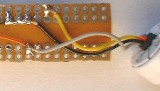 |
Solder the 3 wires to the appropriate places on the circuit board. I'd go right across the 47µF capacitor for +5v and GND, and run the SW7 line straight to pin 3 of U1. In this circuit, I've run a jumper using a clipped resitor lead from pin 3 of U1 back to where you see the yellow wire soldered to. This was because I wanted a bit of slack in all three wires, so I had to keep the connections by the back of the board. |
| * Final Assembly * | |
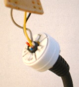
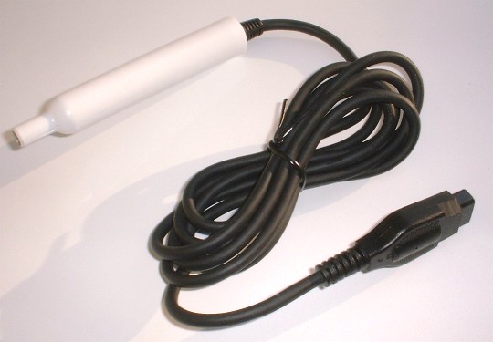
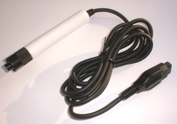
| This is the easy part! Everything
is basically done already...except you still need to slip the circuit
board into the marker casing and push the endcap on. Make sure as you
insert the circuit board that the phototransistor is centered in the case
and is pointing straight out the tip. If it's not, then just slip it out
and re-adjust it until it is. The first picture obviously shows the MVLP without the marker cap. Why would you want to put the marker cap on there anyway? Well, try it, and you'll see why. The first conclusion you'll come to is, "Cool, it's a marker again...and when I pop this cap off there's a totally rad lightpen inside!". Umm, yeah. Well, maybe not... but the functional part I hoped you'd see is the protective cover aspect. It keeps the dust out, and keeps the tip of the marker case from getting mangled. |
|
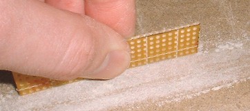
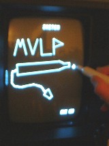 Kind of blury in the dark, but you get the idea ;) |
Time to play! Don't forget to set your brightness properly. The official Vectrex lightpen instructions suggest turning down the brightness from MAX. until the dot in the center of the screen just goes away. You'll find that this is still a little too bright for the MVLP, which is a good thing because you don't have to blast your eyes with day-bright vectors just to get your MVLP to work adequately. You can get a good sense of the sensitivity of the MVLP by firing up Art Master and selecting sketch mode. Then put the MVLP on the '+' on the screen, and slowly pull out and up at the same time. The '+' should track along the MVLP movment. If you can pull the MVLP out way past 1" before the '+' stops, the brightness could be turned down a little. If you can't even pull the MVLP out to 1" then you need to turn the brightness up a bit. The environment lighting will affect the sensitivity also. |
|
|


Home - Vec Store - VecTech - Shop Talk - Preserves - Game Room - Design It - Portals - E-Mail